Apple Releases Apple Watch CAD Drawings
I think they could sell posters of these
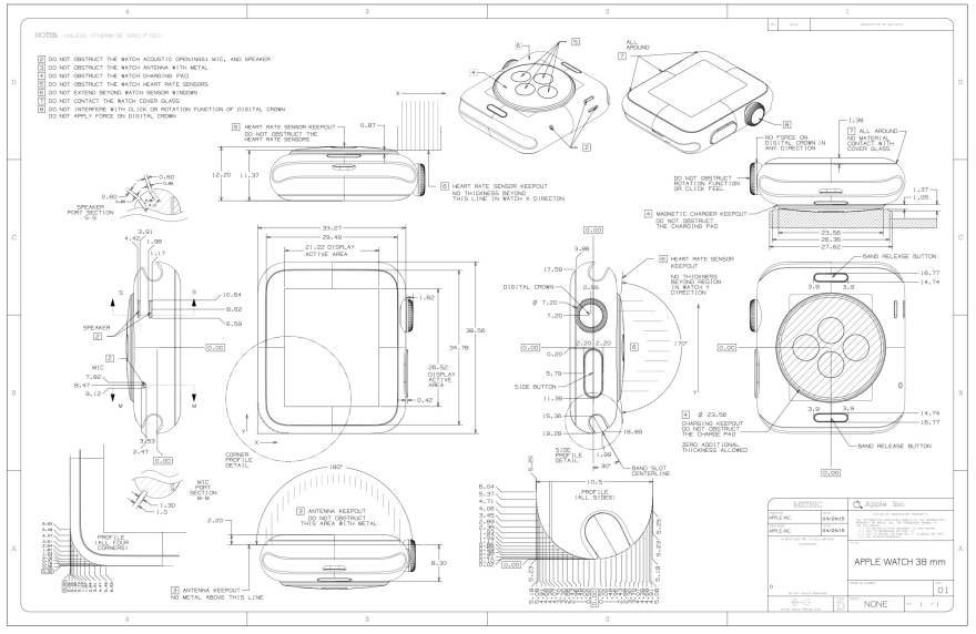
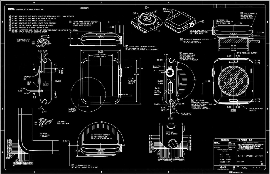
For those of you looking to create watchbands or cases for the Apple Watch, they've released the CAD drawings for both the 38mm and 42mm versions. And boy they are a doozy.
 Enter a caption (optional)
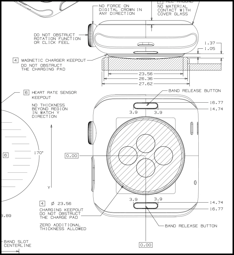
They're filled with "keepouts" warning would-be accessories designers which parts oughtn't be obstructed, to maintain functionality.
 Enter a caption (optional)
To us CAD-reading ID'ers the drawings provide glimpses of numbers we could only have guessed at. Like the corner details:
 Enter a caption (optional)
You didn't think that those were all one radius, did you?
 Enter a caption (optional)
Or the bottom of the side profile?
 Enter a caption (optional)
While the drawings are provided black-on-white…
 Enter a caption (optional)
 Enter a caption (optional)
…Yeah, we inversed them, for no reason other than that they look cool.
 Enter a caption (optional)
 Enter a caption (optional)
You'll find the CAD drawings here, embedded within the PDF.
-
oFavorite This
-
Q5Comment
K
{Welcome
Create a Core77 Account
Already have an account? Sign In
By creating a Core77 account you confirm that you accept the Terms of Use
K
Reset Password
Please enter your email and we will send an email to reset your password.


Comments
Wow.
I was always told by the engineers to measure from a datum point. Are these the actual manufacturing drawings or are the simply a guide for after market manufacturers?.
So, why did Apple go through all the trouble of marking down control points for a spline instead of just giving us the end points and rho value for a conic? It'd have cleaned up the drawing markedly.
Those are probably not conics but splines or even better NURBS curves. You can repersent a correct conic curve with a rational bezier curve of degree 2 but you need higher degree to obtain good cuvature continuity and an aesthetically pleasing connection with the straight line. Also I suspect they just dimensioned points on the curve measured at a regular interval, in a way that every interpolation you could build on them will have a desired error with respect to the actual curve used. It's a common practice in optical design for example.
I agree, it's very frustrating.